JEE Advanced 2017 Paper 1, Question 5
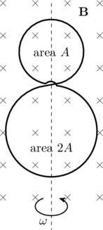
A circular insulated copper wire loop is twisted to form two loops of area ![]() and
and ![]() as shown in the figure. At the point of crossing the wires remain electrically insulated from each other. The entire loop lies in the plane (of the paper). A uniform magnetic field
as shown in the figure. At the point of crossing the wires remain electrically insulated from each other. The entire loop lies in the plane (of the paper). A uniform magnetic field ![]() points into the plane of the paper. At
points into the plane of the paper. At ![]() , the loop starts rotating about the common diameter as axis with a constant angular velocity
, the loop starts rotating about the common diameter as axis with a constant angular velocity ![]() in the magnetic field. Which of the following options is/are correct?
in the magnetic field. Which of the following options is/are correct?

- The emf induced in the loop is proportional to the sum of the areas of the two loops
- The amplitude of the maximum net emf induced due to both the loops is equal to the amplitude of maximum emf induced in the smaller loop alone
- The net emf induced due to both the loops is proportional to

- The rate of change of the flux is maximum when the plane of the loops is perpendicular to plane of the paper
Related Problem: Conducting wire in a magnetic field
Solution
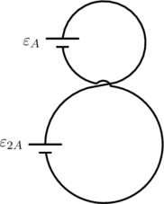
When the loop starts rotating the flux ![]() through both loops decrease. By Lenz’s law, currents will be induced in these loops in such a way as to oppose the change in flux, which in this case means augmenting the magnetic field into the plane of the paper. If the two loops were not connected this would mean a clockwise current flows in both loops, driven by the emfs
through both loops decrease. By Lenz’s law, currents will be induced in these loops in such a way as to oppose the change in flux, which in this case means augmenting the magnetic field into the plane of the paper. If the two loops were not connected this would mean a clockwise current flows in both loops, driven by the emfs ![]() and
and ![]() shown in the figure below. However, the loops are connected in such a way that
shown in the figure below. However, the loops are connected in such a way that ![]() and
and ![]() appear in series and oppose one another resulting in a net emf of
appear in series and oppose one another resulting in a net emf of ![]() . We can calculate this explicitly by Faraday’s law
. We can calculate this explicitly by Faraday’s law
(1) ![]()
since the field ![]() is uniform over both loops. Therefore (A) is incorrect and (B) is correct.
is uniform over both loops. Therefore (A) is incorrect and (B) is correct.

Next, we note that the flux through the loops are maximum when ![]() is perpendicular to the area of the loop, and zero when the loop is parallel to
is perpendicular to the area of the loop, and zero when the loop is parallel to ![]() . Therefore we can quickly identify that
. Therefore we can quickly identify that
(2) ![]()
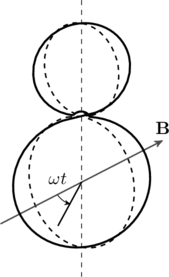
where ![]() is the angle between the loop and the normal to the plane of the loop (see figure). But we’re not done; we need to take the time derivative of the flux as shown in (1) to obtain the net emf,
is the angle between the loop and the normal to the plane of the loop (see figure). But we’re not done; we need to take the time derivative of the flux as shown in (1) to obtain the net emf,
(3) ![]()
This is maximum when ![]() , which is when the plane of the loops is perpendicular to the plane of the paper. So option (C) is incorrect but option (D) is correct.
, which is when the plane of the loops is perpendicular to the plane of the paper. So option (C) is incorrect but option (D) is correct.

Bonus Problem:
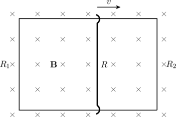
(3.289 of Irodov) A rectangular loop with a sliding connector of length ![]() is located in a uniform magnetic field
is located in a uniform magnetic field ![]() perpendicular to the loop plane (see figure). The connector has a resistance
perpendicular to the loop plane (see figure). The connector has a resistance ![]() and slides with a constant velocity
and slides with a constant velocity ![]() . Neglecting self-inductance of the loop, find the current flowing in the connector. (Hint: Consider the change in flux through each loop separately)
. Neglecting self-inductance of the loop, find the current flowing in the connector. (Hint: Consider the change in flux through each loop separately)

Answer:
(4) ![]()