Buoyancy of connected objects


JEE Advanced 2013 Paper 1, Question 12

A solid sphere of radius R and density \rho is attached to one end of a mass-less spring of force constant k. The other end of the spring is connected to another solid sphere of radius R and density 3 \rho. The complete arrangement is placed in a liquid of density 2 \rho and is allowed to reach equilibrium. The correct statement(s) is (are)

  1. the net elongation of the spring is \frac{4 \pi R^{3} \rho g}{3 k}.
  2. the net elongation of the spring is \frac{8 \pi R^{3} \rho g}{3 k}
  3. the light sphere is partially submerged.
  4. the light sphere is completely submerged.

Solution

Recall that the buoyant force experienced by …

Continue Reading

Bernoulli’s principle in a spray gun

JEE Advanced 2014 Paper 2, Questions 13 and 14

A spray gun is shown in the figure where a piston pushes air out of a nozzle. A thin tube of uniform cross section is connected to the nozzle. The other end of the tube is in a small liquid container. As the piston pushes air through the nozzle, the liquid from the container rises into the nozzle and is sprayed out. For the spray gun shown, the radii of the piston and the nozzle are 20 {\rm~mm} and 1 {\rm~mm}, respectively. The upper end of the container is open to the atmosphere.

Rendered by QuickLaTeX.com

Q.1

Continue Reading

Power dissipated in resistance networks

JEE Advanced 2008 Paper 1, Question 25

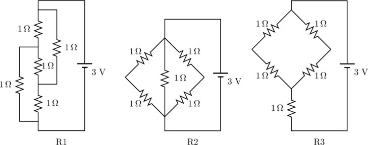
The figure below shows three resistor configurations R1, R2 and R3 connected to 3 \mathrm{~V} battery. If the power dissipated by the configuration R1, R2 and R3 is P1, P2 and P3 respectively, then

Rendered by QuickLaTeX.com

  1. P1 > P2 > P3
  2. P1 > P3 > P2
  3. P2 > P1 > P3
  4. P3 > P2 > P1

Solution

The power dissipated by a resistance network is

(1)   \begin{equation*}   P = \frac{V^2}{R} .  \end{equation*}

The potential applied to all three networks arre the same, so we just need to find the resistances. Of circuits R2 and R3, the latter has a greater resistance since

(2)   \begin{equation*}   % R_3 = 1 \, \Omega + \frac{2 \, \Omega \cdot 2 \, \Omega}{2 \, \Omega + 2 \, \Omega} = 2 \, \Omega ,   R_3 = 1 \, \Omega + \left( \frac{1}{2 \Omega} + \frac{1}{2 \Omega} \right)^{-1} = 2 \, \Omega , \end{equation*}

whereas

(3)   \begin{equation*}   % R_2 = \frac{1 \, \Omega \cdot 1 \, \Omega}{1 \, \Omega + 1 \, \Omega} = 0.5  \, \Omega .   R_2 = \left( \frac{1}{1 \Omega} + \frac{1}{2 \Omega} + \frac{1}{2 \Omega} \right)^{-1} = 0.5 \, \Omega. \end{equation*}

The first circuit can be redrawn in the following way to make the comparison easier.…

Continue Reading