Power dissipated in resistance networks

JEE Advanced 2008 Paper 1, Question 25

The figure below shows three resistor configurations R1, R2 and R3 connected to 3 \mathrm{~V} battery. If the power dissipated by the configuration R1, R2 and R3 is P1, P2 and P3 respectively, then
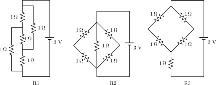
Rendered by QuickLaTeX.com

  1. P1 > P2 > P3
  2. P1 > P3 > P2
  3. P2 > P1 > P3
  4. P3 > P2 > P1

Solution

The power dissipated by a resistance network is

(1)   \begin{equation*}   P = \frac{V^2}{R} .  \end{equation*}

The potential applied to all three networks arre the same, so we just need to find the resistances. Of circuits R2 and R3, the latter has a greater resistance since

(2)   \begin{equation*}   % R_3 = 1 \, \Omega + \frac{2 \, \Omega \cdot 2 \, \Omega}{2 \, \Omega + 2 \, \Omega} = 2 \, \Omega ,   R_3 = 1 \, \Omega + \left( \frac{1}{2 \Omega} + \frac{1}{2 \Omega} \right)^{-1} = 2 \, \Omega , \end{equation*}

whereas

(3)   \begin{equation*}   % R_2 = \frac{1 \, \Omega \cdot 1 \, \Omega}{1 \, \Omega + 1 \, \Omega} = 0.5  \, \Omega .   R_2 = \left( \frac{1}{1 \Omega} + \frac{1}{2 \Omega} + \frac{1}{2 \Omega} \right)^{-1} = 0.5 \, \Omega. \end{equation*}

The first circuit can be redrawn in the following way to make the comparison easier.…
Continue Reading

Resistor network with mirror symmetry

JEE Advanced 2012 Paper 1, Question 12

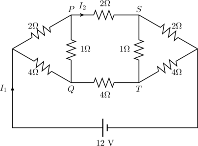
For the resistance network shown in the figure, choose the correct option(s).

Rendered by QuickLaTeX.com

  1. The current through PQ is zero.
  2. I_1 = 3 A.
  3. The potential at S is less than that at Q.
  4. I_2 = 2 A.

Solution

We can speed up the solution by noticing the mirror symmetry of the circuit. Let the current I_1 split into two parts I_a and I_b at the node X (see figure). Similarly, let the currents going into node Y be I_a' and I_b'. If we were to reverse the polarity of the 12 \, {\rm V} battery connected to the circuit, all currents would simply reverse direction, but their magnitudes would remain the …

Continue Reading