JEE Advanced 2014 Paper 1, Question 9
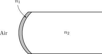
A transparent thin film of uniform thickness and refractive index ![]() is coated on the convex spherical surface of radius
is coated on the convex spherical surface of radius ![]() at one end of a long solid glass cylinder of refractive index
at one end of a long solid glass cylinder of refractive index ![]() , as shown in the figure. Rays of light parallel to the axis of the cylinder traversing through the film from air to glass get focused at distance
, as shown in the figure. Rays of light parallel to the axis of the cylinder traversing through the film from air to glass get focused at distance ![]() from the film, while rays of light traversing from glass to air get focused at distance
from the film, while rays of light traversing from glass to air get focused at distance ![]() from the film. Then
from the film. Then

Related Problem: Lensing by oil on water
Solution
We can solve this problem using the formula for refraction at spherical surfaces (see (27-3) of this lecture or the last equation on this page),
(1) ![]()
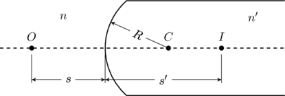
In this equation the object is at a distance ![]() from the refracting surface in the medium of index
from the refracting surface in the medium of index ![]() , and the image is at a distance
, and the image is at a distance ![]() from the same surface in the medium of index
from the same surface in the medium of index ![]() (see figure below). The sign convention for refracting surfaces are the same as that of lenses.
(see figure below). The sign convention for refracting surfaces are the same as that of lenses.

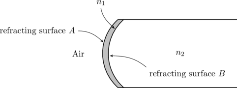
The present problem can be solved two ways. The first method involves applying (1) twice, once at the surface ![]() separating air from the medium with index
separating air from the medium with index ![]() , and then at the surface
, and then at the surface ![]() that separates
that separates ![]() and
and ![]() (see figure below). This requires no cleverness, but it illustrates how to work with sign conventions for refracting surfaces. So we will try it.
(see figure below). This requires no cleverness, but it illustrates how to work with sign conventions for refracting surfaces. So we will try it.

We first consider rays parallel to the axis traveling from air to glass. Such rays are produced by an object kept at infinity. Therefore, at the surface ![]() we have
we have
(2) ![]()
The image at ![]() is the object for the second surface, and is located at
is the object for the second surface, and is located at ![]() . This approximation is valid since the medium
. This approximation is valid since the medium ![]() is thin. The difference in sign between
is thin. The difference in sign between ![]() and
and ![]() is due to the fact that object distances are negative behind the surface whereas image distances are postive there (see this table). Next, we apply (1) on the second surface
is due to the fact that object distances are negative behind the surface whereas image distances are postive there (see this table). Next, we apply (1) on the second surface ![]() ,
,
(3) ![]()
Next, we keep the object at infinity in the medium ![]() . We will take the
. We will take the ![]() side as the front of the refracting surface when applying the sign conventions. Refraction through the surface
side as the front of the refracting surface when applying the sign conventions. Refraction through the surface ![]() produces an image at
produces an image at ![]() such that
such that
(4) ![]()
Note how the sign of the radius of curvature has changed since the center of the spherical surface is on the object side now (see table). The image at ![]() will be the object for the surface
will be the object for the surface ![]() , at a distance
, at a distance ![]() . Applying (1) at
. Applying (1) at ![]() ,
,
(5) ![]()
Substituting ![]() in the expressions (3) and (5) we see that
in the expressions (3) and (5) we see that ![]() . Therefore options (A) and (C) are correct.
. Therefore options (A) and (C) are correct.
Alternate solution: Notice that the expressions (3) and (5) are independent of ![]() . This tells us that the coating had no affect on the location of the focal points of the refracting surface
. This tells us that the coating had no affect on the location of the focal points of the refracting surface ![]() . To understand why, we can consider the coating as a convexo-concave lens (or meniscus) as shown in this figure. However, the radii of curvature of such a lens are equal,
. To understand why, we can consider the coating as a convexo-concave lens (or meniscus) as shown in this figure. However, the radii of curvature of such a lens are equal, ![]() , which makes the focal length infinity by the Lens Maker’s formula,
, which makes the focal length infinity by the Lens Maker’s formula,
(6) ![]()
In other words, the coating has no effect on the overall focal length, since
(7) ![]()
Therefore, we can calculate ![]() and
and ![]() by simply assuming that the coating is absent. Then, the surface
by simply assuming that the coating is absent. Then, the surface ![]() that separates air from
that separates air from ![]() , which means parallel rays from air to glass will converge at
, which means parallel rays from air to glass will converge at ![]() such that
such that
(8) ![]()
and, rays from the glass to air will converge at
(9) ![]()
This is exactly the same answer we obtained above, but this approach is quicker.